Series
180
Grease- Max. flow
- 5.5 m³/h
- Max. head
- 200 m
- Motor power
- 1.5–4 kW
- Lubrication
- Grease
- Max. inlet pressure
- 1.5 MPa
For low-flow requirements within 5.5 m³/h and 200 m head.
Model reference
Compare flow, head and inlet pressure. Select the speed, pick-up tube, materials and motor for the liquid and installation.
The table shows the limits of each standard series. Read flow, head and motor power together. The selected speed and tube determine the actual operating point and its performance curve.
Check inlet pressure separately from discharge head. The seal is on the inlet side, so its selection also uses the suction pressure.
| Series | Max. flow m³/h | Max. head m | Motor kW | Max. inlet MPa |
|---|---|---|---|---|
| 180 | 5.5 | 200 | 1.5–4 | 1.5 |
| 260 / 260G | 12 | 400 | 4–15 | 1.5 |
| 280 | 30 | 430 | 7.5–55 | 1.5 |
| 320 | 30 | 450 | 11–55 | 1.5 |
| 390 | 56 | 800 | 18.5–160 | 1.5 |
| 420 | 70 | 1,050 | 22–110 | 1.5 |
| 450 | 20 | 500 | 37–55 | 0.6 |
Choose the operating point from the curve for the selected speed and tube.
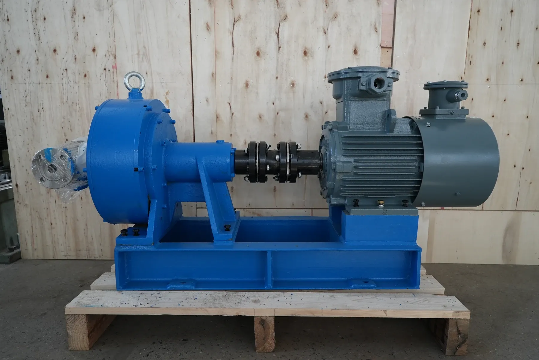
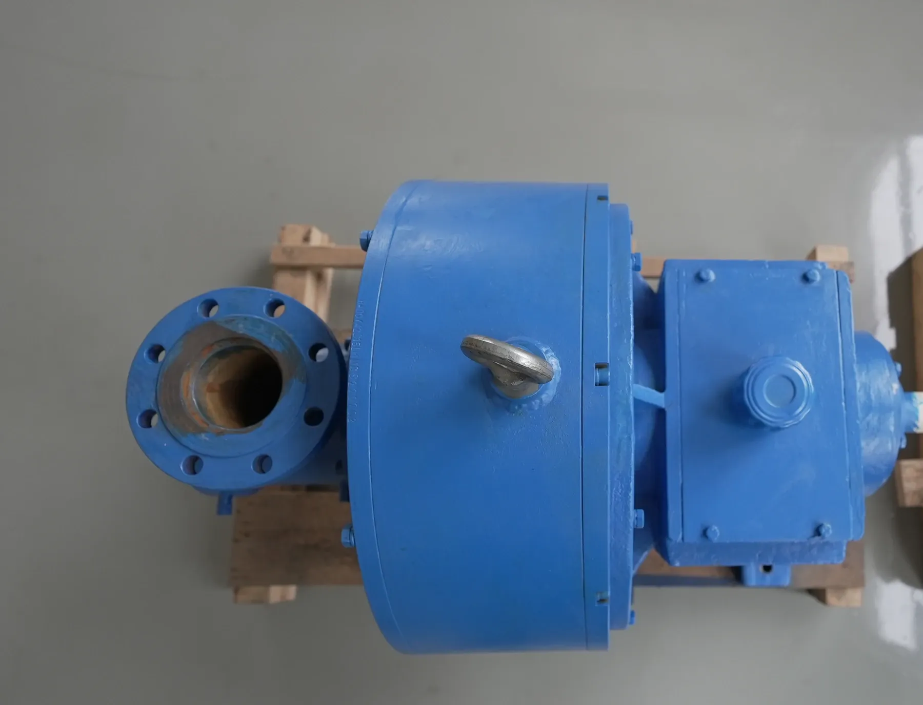
For low-flow requirements within 5.5 m³/h and 200 m head.
For flows within 12 m³/h and head up to 400 m.
For flows within 30 m³/h and head up to 430 m.
For the same 30 m³/h flow limit as series 280, with head up to 450 m.
For higher-head requirements within 56 m³/h and 800 m.
The highest standard limits: 70 m³/h and 1,050 m head.
For flows within 20 m³/h and 500 m head, with an inlet-pressure limit of 0.6 MPa.
Series 180 and 260 / 260G use grease lubrication. Series 280, 320, 390, 420 and 450 use oil-bath lubrication. Apply the oil-level and oil-change checks only to oil-bath units; grease units require their own lubrication procedure.
Wetted parts can be carbon steel, ductile iron, 304 and 316 stainless steel or duplex stainless steel. Pick-up tubes use 17-4PH stainless steel. The liquid properties and project requirements determine the material.
Corrosion and particle wear require separate checks. Select chemically resistant wetted materials for a corrosive liquid. A wear-resistant tube coating protects against hard particles.
Single and double cartridge seals are available. The seal is exposed to inlet pressure; the pick-up tube passage carries the high discharge pressure.
API mechanical seals and flushing systems configured to API standards can be supplied. Project options include Plan 52 and Plan 53. The proposal defines the seal type and flushing connections.
Standard speed is 2,900–6,300 rpm. Speed and tube size determine performance; motor power is checked at the required flow and head.
Supply can be a bare-shaft pump or a set with motor, base, coupling and guard. A complete skid can include piping, valves, instruments and controls.
Replacement flanges can match existing pipes. The base and drive are checked against the installation, with outline drawings for installation review.
Custom single-stage head up to 1,500 m and flow up to 100 m³/h have been supplied. These are non-stock configurations with a supply period longer than six months. High-head versions require a high-voltage motor and power supply.
Include the liquid, temperature, density, viscosity and particles. Give the normal flow and head, and any minimum or maximum demand. For pressure readings, identify the measurement locations.
Add the inlet pressure, required motor supply and seal-flushing connections. For a replacement, include the nameplate model and the pipes, base or motor you want to retain. A curve and outline drawing are provided for the selected speed and tube.
Send the operating point for selectionThe next step
Liquid, flow, head and inlet conditions.
For a replacement, add the model on the nameplate.